Nov. 14, 2023
Research on Zero Emission Gas Turbine for Advanced Air MobilityAchieving Dream Mobility through Hydrogen Combustion & Air Bearing Technology
At the time of the company's founding, Toyota Motor Corporation (Toyota) was considering manufacturing not only vehicles, but also aircraft*1. In these days, aircraft technology is advancing, and there are growing expectations for more personalized and electric-powered aircraft in the future. Yes, it's an "Advanced Air Mobility (AAM)," a so called "flying car."
On the other hand, did you know that the engine for the first hybrid vehicle technology created by Toyota was a "gas turbine"? A new challenge to utilize this gas turbine technology has begun in our Frontier Research Center, targeting various applications such as vehicles, ships, and emergency generators. Currently our development focus is on AAM.
-
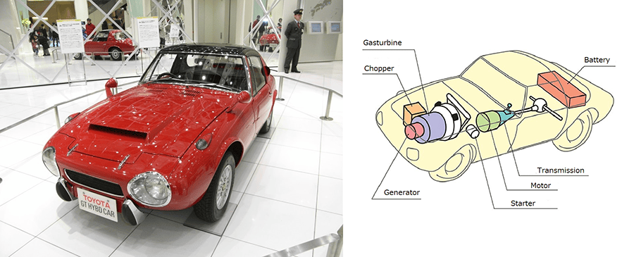
- Figure 1 Toyota Sports 800 Gas Turbine Hybrid Vehicle
Exhibited at the 22nd Tokyo Motor Show in 1977
Proposal of a gas turbine aiming to achieve AAM
In order to achieve AAM, various battery-powered aircraft are currently under development around the world. While their development is spectacular, the weight and capacity limitations of batteries may require a propulsion or power generation technology that can provide greater convenience and safety.
-
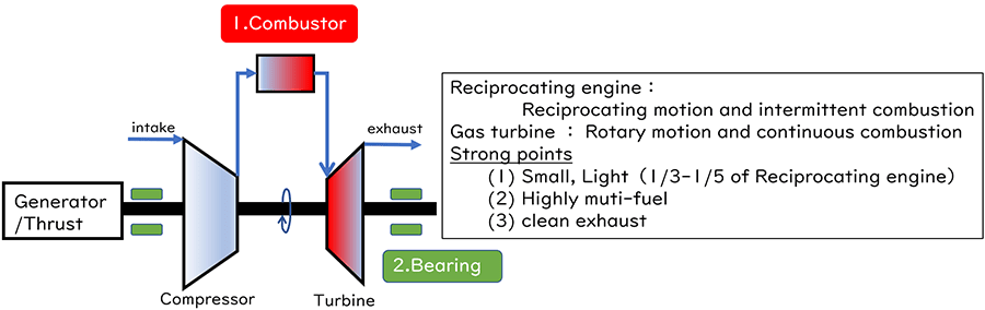
- Figure 2 Outline of gas turbine
Gas turbines are generally used as propulsion systems for aircraft due to their small size and lightweight characteristics, and Toyota has been developing and accumulating technology since the 1970s as one of the driving forces of the automobile. The Frontier Research Center is focusing on this small and light gas turbine as one of the multi-pathways toward achieving AAM and promoting research and development.
There are two main technical focuses in AAM that we currently assume are:
- Carbon neutrality
- Auxiliary equipment gets heavier as it is downsized (larger as a percentage of the total)
The Frontier Research Center is taking on the challenge of "hydrogen combustion" for (1). And for (2), we are taking on the challenge of developing "air bearing" technology. We will introduce these two points in this report.
Hydrogen tends to burn with too high velocity. The challenge is how to make it burn well.
―First, we asked Mr. Minami and Mr. Tatebayashi, who are in charge of hydrogen combustion, about the key points of development. Toyota has technologies such as MIRAI that use hydrogen to generate electricity. Are you trying to burn hydrogen inside a gas turbine?
-
- Figure 3 Members of the combustion development team
Bottom left: Tatebayashi, Bottom right: Minami
- Minami
- Yes. Let me explain why we focused on hydrogen first. In 2021, Toyota achieved the world's first mono-fuel ammonia combustion in gas turbine*2-8. Mono-fuel ammonia combustion means burning only ammonia. Ammonia is expected to be a carbon-neutral fuel because it does not produce carbon dioxide when it is burned. This ammonia combustion technology is supposed to be used for stationary generators. Because ammonia is toxic, we assume that a more suitable fuel would be expected for personal mobility vehicles such as flying cars, which is our current target.
So, we focused on hydrogen as another carbon-neutral fuel. Hydrogen is said to be "clean" because it produces only water when burned. However, internal combustion engines have the tendency to produce "NOx," which causes acid rain and is harmful to the respiratory system. In addition, hydrogen burns extremely fast compared to other fuels, so there is a risk of meltdown of parts due to backflow of flame, which is called "flame flashback." The engineering concern is that it is easy to cause flashback when trying to reduce NOx, and vice versa. Hydrogen is a very tricky fuel due to its flammable properties, but that makes it interesting for engineers.
-
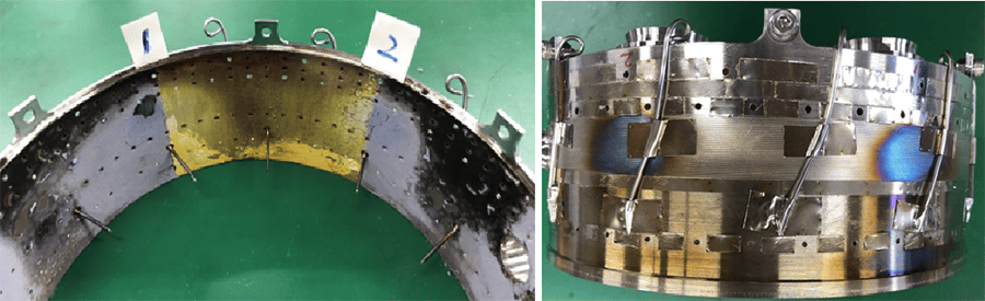
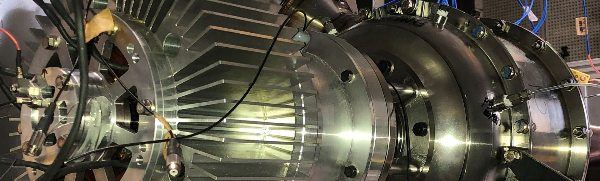
- Figure 4 Hydrogen combustor
Left: Inside of combustor liner (color: thermal paint), Right: Outside of combustor liner
Low NOx requires lean combustion (equivalent ratio of 0.4 or less) by premixing method. Hydrogen has a lower density than air (one-tenth), so the mixing of the two is worse, and NOx is more likely to be produced, especially in the low-velocity region. For the low-velocity region, a hydrogen flame with a high combustion speed (hydrogen 300 cm/sec, city gas 40 cm/sec) causes backflow (=flashback), resulting in meltdown of parts (the black area in Figure 4 is the meltdown area).
―That is reassuring indeed. When most people think of hydrogen, they think of explosions, but is there any way to manipulate such extremely fast-burning hydrogen flames at will?
- Tatebayashi
- Yes, in fact, hydrogen combustion can be controlled by adjusting the ratio of air to hydrogen mixture, flame velocity, and other factors. In the combustion design, we use the Computational Fluid Dynamics (CFD), a numerical analysis method to simulate combustion phenomena, to virtually study the process. However, the accuracy of conventional simulations has been poor, resulting in a continuous process of trial and error.
Currently, we are jointly conducting research with Prof. Nobuyuki Oshima*9 of Hokkaido University and Numerical Flow Design Co., Ltd.*10 to take on the challenge of a CFD method called the Large Eddy Simulation (LES) + 2-scaler flamelet, which is suitable for gas turbine combustion. In this joint research, we are utilizing the High Performance Computing Infrastructure (HPCI), a group of supercomputers that can only be available for use by universities and research institutions.
- Movie 1 Hydrogen-combustor CFD
Left: Temperature isosurface of flame, Right: Temperature distribution (Red: high, Blue: low)
In hydrogen combustion design, it is important to accurately simulate (CFD) the complex flow and combustion of a premixed and diffusion combustion system. To solve these issues, we are collaborating on a new method that combines an improved combustion model (2-scaler flamelet approach) at Oshima Laboratory of Hokkaido University and a large-eddy simulation (LES) model that can accurately capture unsteady turbulent flow fields. The complex flow of a wrinkle-shaped high-temperature region can be seen, and a strong turbulent combustion field can be analyzed.
―I see. Indeed, the video shows the hydrogen flame moving in a rather complex manner.
- Tatebayashi
- We are not only working on advanced analytical methods, but also on combustion visualization equipment. In this way, we are working to make hydrogen combustion design a hands-on process, integrating the real with the virtual.
-
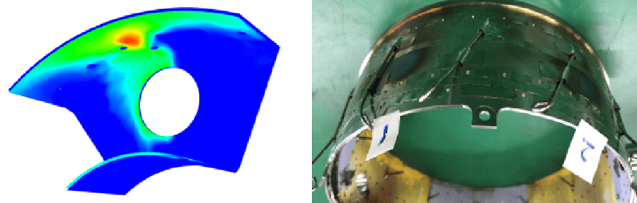
- Figure 5 Left: CFD results liner temperature distribution, Right: Liner after testing
The CFD shows some areas where the temperature rises locally, suggesting a tendency for hydrogen combustion to be less uniform (left). After the test, localized melting damage was observed on the parts, which shows the validity of CFD. This localized high-temperature zone can cause damage to components as well as NOx emissions. Therefore, we are developing a component design that minimizes this localized high-temperature zone.
Flying bearings. The unique design technique of air thickness on the order of 10 μm.
In the small class of gas turbine engines, such as those used in AAM, auxiliary equipment such as the oil system has to be as large as the engine itself. Therefore, the downsizing of the auxiliary equipment is important. The Frontier Research Center is taking on the challenge of developing a bearing that can be used without oil, called an air bearing, as a technology to reduce the number of auxiliary devices to zero. We interviewed Mr. Nakao and Mr. Hatano who are in charge of this development.
-

- Figure 6 Members of the air bearing development team
Far-left: Hatano, Second from far-left: Nakao
―You said you wanted to reduce the number of auxiliary parts to zero, but I think the bearing is the part that makes the shaft in a machine rotate smoothly and requires oil. What did you use instead of oil?
- Nakao
- Actually, that is the air. The air will support the shaft that rotates at high speed. Generating this magic air layer will be the design know-how.
-
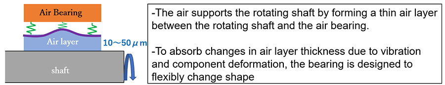
- Figure 7 Outline of air bearing
―I see, if the shaft can be supported by air, there is no need for oil and no unnecessary friction, so quiet and comfortable mobility can be achieved. However, if it were only air, would it not be stable?
- Hatano
- A stable air layer is about 10 µm thick, and the bearing to maintain that layer thickness consists of a plate about 50 µm thick. The air bearing maintains this proper air layer thickness by providing it with spring-like properties. The most difficult aspects of the design are the following:
- Consideration of the relationship between air layers (fluid) and air bearings (structure)
- Air bearing fabrication know-how to ensure spring properties
Since an error in either case will not result in a stable air layer, research is being conducted to improve design and fabrication techniques.
-
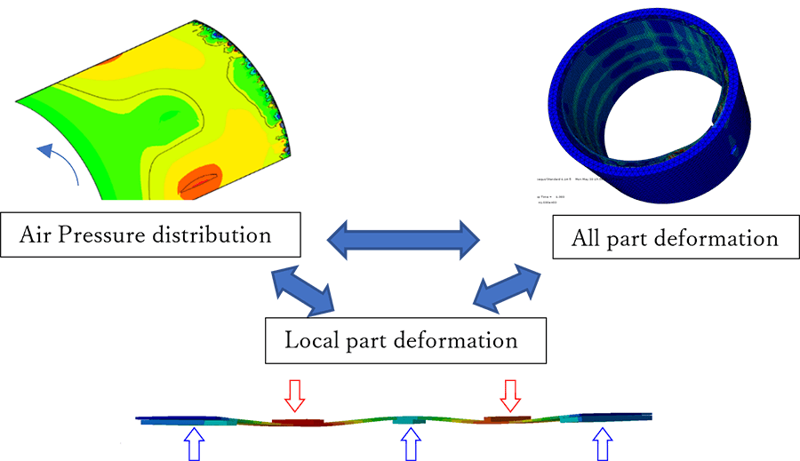
- Figure 8 Fluid and structure analysis
When the air pressure changes, the internal spring undergoes deformation. The deformation affects multiple directions, resulting in deformation of the entire bearing. This deformation leads to a change in the aerodynamic force and also causes deformation of the spring. In air bearing design, we are working on computational fluid dynamics (CFD) and structural deformation (FEM) analysis with high accuracy and coupled analysis (FSI: fluid structure interaction) to capture the interaction between the two.
-
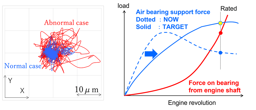
- Figure 9 Left: Trajectory of the shaft supported by air bearing (actual measurement),
Right: Force applied from the engine shaft to the air bearing and the bearing supporting the shaft (image)
Under certain conditions, the rotating shaft may vibrate abnormally, resulting in damage to the shaft system (above left). Since the air bearing supports the shaft with a very thin air layer on the order of 10 μm, any shaft movement greater than the air layer thickness will damage the shaft and bearing. The figure on the right shows the force applied to the bearing and the force supporting it, which vary with rotation speed. Because gas turbines rotate at very high speeds, the force to support the shaft may decrease due to the heat generated by the supersonic speed inside the bearing and the heat generated by the heat transfer of combustion gas (dotted line in the figure on the right). In our research, we are developing cooling structures (spring shapes, spring layering) and coating techniques to avoid these problems, and we are also making measurements that can capture dynamic deformation on the order of microns.
Future perspectives
Although there are many technical challenges, we will continue to refine and propose gas turbine technology as one of the technological multi-pathways to fly freely in the sky. It is important to foster technology and engineers who are second to none, and to have the passion and will to achieve this. We will continue to set high goals and challenge with highly humility.
-
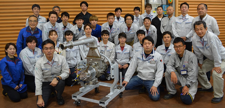
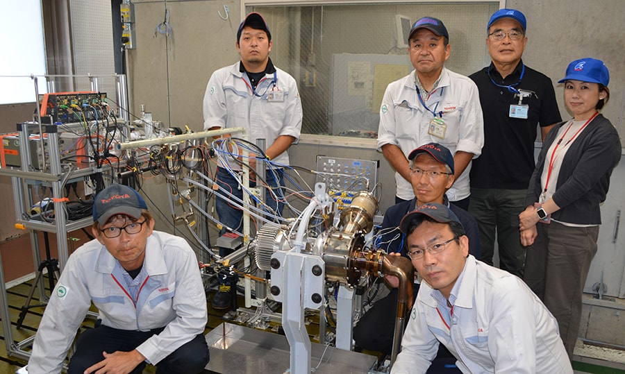
- Figure 10 Project members
Author
Takahiro Minami
Group Manager, Gas Turbine Group, R-Frontier, Frontier Research Center
Reference
| *1 | http://www.toyota-global.com/company/history_of_toyota/75years/text/taking_on_the_automotive_business/chapter2/section5/item9.html |
|---|---|
| *2 | "Ignition of 100% ammonia in a swirling burner for a 50 kW-class micro gas turbine", the 13th Asia-Pacific Conference on Combustion 2021 |
| *3 | "Characteristics of Ammonia Spray Injected by Pressure-Swirl Atomizers", the 15th Triennial International Conference on Liquid Atomization and Spray Systems |
| *4 | "Development of 50kW Class Liquid Ammonia-fired Micro Gas Turbine", Proceedings of the 49th Annual Conference of GTSJ |
| *5 | "Starting the gas turbine by supplying NH3 using the on-board reformer", Proceedings of the 50th Annual Conference of GTSJ |
| *6 | "Demonstration of Power Generation of 50kW Class Micro Gas Turbine by Supplying Liquid NH3", Proceedings of the 50th Annual Conference of GTSJ |
| *7 | "Effects of Precombustion in Liquid Ammonia Combustors", the 60th Combustion Symposium |
| *8 | "EXPERIMENTAL INVESTIGATION OF THE STABILITY OF LIQUID/GASEOUS AMMONIAFIRED MONO-FUEL GAS TURBINE", Proceedings of ASME Turbo Expo 2023 |
| *9 | Computational Fluid Engineering Laboratory, Hokkaido University Graduate School of Engineering |
| *10 | Numerical Flow Design CO., LTD. |
Contact Information (about this article)
- Frontier Research Center
- frc_pr@mail.toyota.co.jp
RELATED CONTENT
MOST POPULAR